Executive Summary/
What Was Accomplished
-
Demonstrated the ability to complete a systematic approach to a static structural analysis in ANSYS, balanced with hand calculations
-
Determined that the stresses in the bolt/nut and nozzles are below their elastic limit and the gap that develops between the jointed parts is not of concern for the O-ring to possibly lodge itself in between the flanges, causing flange leaking, as it is currently designed
Biggest Takeaways/
Lessons Learned
-
The importance of validating an analysis as much as possible to hand calculations to make sure that the effects that are harder to capture with hand calculations, such as gapping, are likely correct in the model.
-
Using multiple load steps to help the model solve and be able to analyze results individually.
-
The results from a sensitivity study can help drive decisions in the re-design of a product by identifying which model input affected the solution the most.
Transferrable
Skills
-
Modeling thermal strains
-
Modeling bolt preload
-
Utilizing the gapping tool
-
Manually specifying bonded and frictionless contacts surfaces
-
Interpreting analysis results and comparing them to hand calculations
-
Using standards to drive engineering decisions
-
Performing a sensitivity study of model inputs

The following project is a guided exercise from the free online course, "A Hands-on Introduction to Engineering Simulations CornellX: ENGR2000X". All work and analysis produced is my own.
Table of Contents
Introduction
Problem Specification
Given Parameters
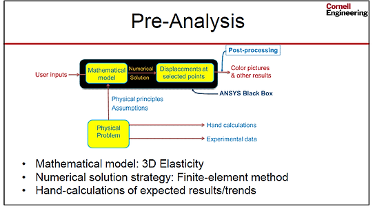
Pre-Analysis
Mathematical Model
Governing Equations
Domain (Geometric Model)
Boundary Conditions
Hand Calcs of Expected Results
Model Setup
Mesh
Loads
Contact Surfaces
Numerical Solutions/Results
Equivalent (Von Mises Stresses)
Total Deformations
Gapping
Verification
Compare Results to Hand Calcs
Mesh Refinement
Model Sensitivity Study
Regeneration Channel Force
Bolt Preload
Coefficient of Friction Between Flanges

Introduction
Problem Specification:
The Saturn V rocket that carried people to the moon is one of the most powerful machines ever built; particularly, there is tremendous power packed into the first stage rockets that were powered by five F1 engines. The bolted flange joint that connects the mid and lower parts of the F1 engine nozzle are analyzed in this project.
Analysis Goals:
-
Access the margin of safety in the stress seen in the flange nuts/bolts
-
Determine the gap that develops between the jointed parts when the assembly is fully loaded
-
Identify any areas of significant stress on the nozzles

Given Parameters:
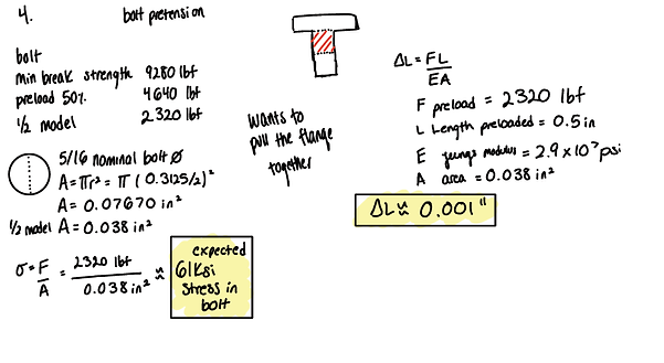
The pressure due to the exhaust gas in the nozzle is calculated using 1D gas dynamics. It is assumed to vary linearly along the nozzle z-axis. The pressure at the exit (z=0) is 12.17 psi and the pressure at the entrance to the mid-nozzle is 47.72 psi. The regeneration channels are omitted in the model; in exchange, a free body diagram is used to deduce the equivalent forces on the mid nozzle and lower nozzle (the upper nozzle is not modeled here). This force pair is modeled as two separate forces, each of 1000 lbf, acting on the nozzle flange. The gas temperature is 700 degree F which causes thermal strain. It is assumed that the bolt is pre-loaded to 50% of its breaking strength.

Pre-Analysis
Mathematical Model:
The simulation is a static structural analysis, utilizing the 3D elasticity equations to obtain the displacement and stress fields; these governing equations are based on the physical principle of equilibrium of an infinitesimally small chunk of material within the geometry/model. The mathematical model is composed of governing equations, a domain, and boundary conditions.
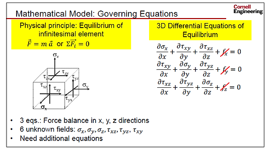
Governing Equations:
3D Differential Equations of Equilibrium
3D Hooke’s Law: (relates the stresses to the strains; assumes the material remains in the elastic range and is isotropic)
This model also includes a thermal strain term and a bolt preload term which will be turned on in the analysis as well.

Strain-Displacement Relations: (assumes small strains)

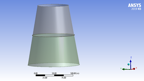
Domain (Geometric Model):
Due to the symmetry of the model, it is advantageous to reduce to model to 1/400 of its full size to only simulate half of one nut and bolt assembled to the mid and lower nozzle. This saves computation time and allows the model to be created within the node limit of the student license.
Domain (four parts)
-
Mid Nozzle
-
Lower Nozzle
-
Bolt
-
Nut

Boundary Conditions:
There are two essential boundary conditions:
-
The symmetry due to periodicity creates a frictionless support on the front and back symmetry planes
-
The top surface of the mid nozzle is constrained by a frictionless support to approximate its connection to the upper nozzle, which is not modeled
There are three natural boundary conditions:
-
Pressure due to the propellant, varying axially along the inside wall of the nozzles and in the resulting gap at the flange
-
A force from the regeneration channels
-
Traction at the contact surfaces
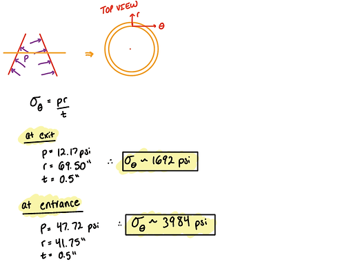
Hand Calcs of Expected Results:
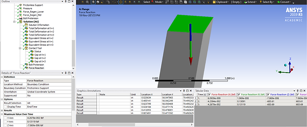
1. Reaction at the Frictionless Support in the Axial Direction at the top of the Mid Nozzle

2. Hoop Stress (Circumferential Direction) Using Pressure Vessel Theory
3. Thermal Strain Deformation at the Exit of the Lower Nozzle

-
Bolt Preload (assumes the flanges are infinitely rigid, which they are not in practice)
Model Setup
Mesh:
Fairly coarse mesh; however, we must stay within the student license limit of 32000 nodes;
Body Sizing of 0.3" used on the nozzles
Body Sizing of 0.075" used on the bolt and nut
Mesh control - method - hex dominant - on all four bodies


Load Steps:
3 Load Steps
-
Bolt preloads, just tightening the bolts
-
Apply propellant pressure and the separating forces due to the regeneration channels
-
Thermal strains applied to all the bodies
Loads will accumulate at the end of the three load steps

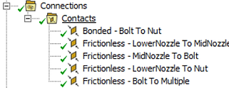
Contact Surfaces:
Specifies the traction at the boundaries.
The bolt to nut bonded connection best simulates the torqued bolt. The rest of the contacts are frictionless, meaning the two surfaces can slide relative to one another but cannot penetrate. Frictionless is generally more conservative in it's results and will give the worst case for gapping (verified in the sensitivity study), and simplifies the model by taking friction out of the equation.


Numerical Solutions/Results
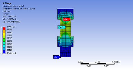
Equivalent (Von Mises) Stress:
All loads are applied (time step 3).
Compare stresses in the model with the capability of the materials.
Material Source: MIL-5 Handbook
1.) Nut and Bolt - A-286 Steel


From the plot above, at 700F the yield strength of A-286 Steel is ~85% of room temperature strength
Room temperature strength is 150,000 PSI
Therefore at 700F, strength is 127,500 PSI
Operating stresses are around 70,000 PSI or below in the bolt, so below the yield strength. FOS of about 1.8.
There are small stress concentrations at the edges of the model which are likely singularities.
2.) Nozzles - 300 Series Stainless Steel


From the plot above, at 700F the yield strength of 300 Series Stainless Steel is ~60% of room temperature strength
Room temperature strength is 30,000 psi
Therefore at 700F, strength is 18,000 PSI
Stress values in range of 4000-8000 PSI are below yield strength. FOS 2.25.
There is a stress concentration at the bearing location between the bolt and flanges. That area will be studied during the mesh refinement.

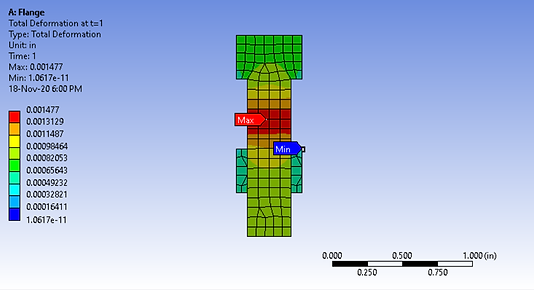
Total Deformations:

Total Deformation; Scaled x100 to verify the model is "moving" as expected.

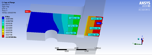
Gapping:
Generally, an allowable gap for this type of nozzle of 5-10 thousands of an inch is okay. The area is green is about 0.005, indicating it is on the verge but wouldn’t expect the O-ring to possibly lodge itself in between the flanges, causing flange leaking.
A design change to decrease gapping would be increasing the bolt preload, add washers, larger flange radius, or a thicker flange.

True Scale visualization of the gapping.

Verification:
1. Reaction at the Frictionless Support in the Axial Direction at the Top of the Mid Nozzle
Hand Calc: 720 lbf
ANSYS: 684 lbf
Percent Difference: 5%
2. Hoop Stress (Circumferential Direction)
At exit:
Hand Calc: 1692 PSI
ANSYS: 1698 PSI
Percent Difference: 0.3%

At entrance:
Hand Calc: 3984 PSI
ANSYS: 3734 PSI
Percent Difference: 6.5%
ANSYS: 4041 PSI
Percent Difference: 1.4%

3. Thermal Strain Deformation at the Exit of the Lower Nozzle
Hand Calc: 1.008"
ANSYS: 1.0984"
Percent Difference: 9.0%

4. Bolt Preload
Stress in the Bolt
Hand Calc: 61 KSI
ANSYS: 61.5 KSI
Percent Difference: 2.5%
Elongation in the Bolt
Hand Calc: 0.001"
ANSYS: 0.0015"
Percent Difference: 50%
Results are still reasonable
Because many of the hand calc are validated, can conclude that the model is correctly solved and that the effects that are harder to capture with hand calculations, such as gapping, are likely correct in the model as well.
Mesh Refinement:
It is possible to chop the mesh up into a purely hex mesh, requiring approximately 80,000 nodes to converge which is well above the 32,000 student license limit. The images of the mesh refinement were not provided within the course material; however, the instructor indicated that the areas of stress concertation in bolt and flange were singularities that are not of concern to the success of the final product.
Model Sensitivity Study
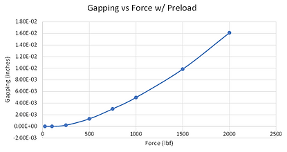
Regeneration Channel Force:
Explore how the regeneration force affects the gapping. Recall that in our base case this force was 1,000 lbf. These forces are changed to 2,000 lbf. Leaving all other inputs the same, the model is re-solved.

Results
The gap increased approximately by a factor of 3.
An increase in the regenerative force applied on the flanges strongly correlates with an increase in gapping. The model is run several more times at different force values. In the absence of pre-load, the flange gapping will linearly increase with load. This makes sense with beam bending theory. With a bolt pre-load, the gapping behaves quadratically because of the additional clamping. In application, if the gapping becomes too large, the seal O-ring could lodge itself in between the flanges, causing flange leakage. Thus the in a re-design the flange thickness, bolt choice, and seal type are functions of the regenerative force.

Bolt Preload:
Explore how changing the bolt preload affects the gapping. Thee regeneration channel forces are changed back to 1,000 lbf. The bolt preload applied was 2,320 lbf. That value is cut in half to 1,160 lbf. Leaving all other inputs the same, the model is re-solved.


Results
The gap increases by a factor of 1.25. A significant change in the bolt preload does not have a significant effect of the gapping for this geometry.
Coefficient of Friction Between Flanges:
The contacts between the flanges were modeled with frictionless contacts; in reality, there will be friction at the contact surfaces that will prevent them from easily sliding freely. The contacts are changed to frictional contacts with a coefficient of friction of 0.5. The coefficient of friction will depend heavily on the specific material and the surface quality of the flanges; however, this change is just to see its effect on the solution for now.
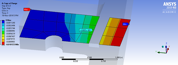
Frictionless Gap: 0.0049734"
Frictional Gap: 0.048885"
Percent difference: 2%
Minimal change, frictionless giving a higher gapping and more conservative result.