EML4502 UF MAE Capstone Design - Part 2
University of Florida
August 2020 - December 2020
Executive Summary/
What Was Accomplished
-
Wrote 7 test plan procedures, purchased and configured equipment, and conducted tests to validate requirements for a human lift and harness system for the UF Nonlinear Controls and Robotics (NCR) Group
Biggest Takeaways/
Lessons Learned
-
The professor organized and treated this class like an industry project to facilitate communication and sub-team collaboration. Progress of the project relied on cooperation and scheduling of the entire team.
-
Due to Covid-19 health and safety protocols causing scheduling delays and tests being unable to be performed, I learned to accept was out of my control and control what I could by helping prepare test plans for future students to use.
Transferrable
Skills
-
Writing test plan procedures
-
Sourcing and purchasing equipment to meet specifications
-
Strain gauge testing
-
Tensile testing
-
Thermal imaging
-
Vibration standards
-
Analyzing test results and adjusting designs if needed
Introduction
At UF the mechanical senior design curriculum takes place in two parts across two semesters. The first part is a complete paper design and analysis of a predetermined product for a customer with a given set of requirements. View the first part of the project here. Then, the customer and UF faculty select 2 to 3 of the designs from the first part to enter into the manufacturing and testing phase.
During the Fall of 2020 I was a part of a 4 member testing team focused on drafting test plans, purchasing hardware, and performing tests to verify the manufactured product met engineering analyses and the customer requirements. Meanwhile, other teams were focused on streamlining the manufacturing and assembly of the product.
This project faced challenges due to the design shops health and safety protocols for the Covid-19 pandemic causing work backlog and schedule delays. The assembly was never fully completed during my time with the project which prevented some of the tests that required the fully assembly to be loaded from being completed; however, a considerable amount of work was able to be accomplished despite these setbacks. If the test was not conducted, a test plan was left for future engineers to complete the remaining work.
Final Product Overview
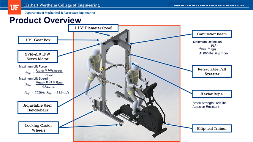

Servo Motor Gearbox Test
The purpose of this test was to quantify the capabilities of the SVM-210 servo motor with 10:1 reducer. A static motor torque test was performed to ensure the system could sustain the patient at rest. The test used an arm on the motor shaft to apply a force to a scale. A 3D printed PLA arm was made to quickly facilitate the test but fractured before meeting the requirement, so an aluminum arm was manufactured using the water jet machine. The aluminum arm reached a load of 95.5 lb at 4.30" which meets the requirement specified by the Dynamic Weight Offset Team.

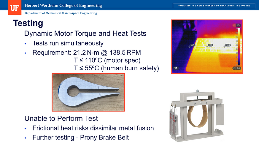
A dynamic torque test was planned to generate a torque and power curve and determine if the motor can keep up with the oscillatory motion of the patient; however, the test was not performed last minute due to concerns with the testing setup causing frictional welding of the test clamp to the motor arm shaft. Further testing in the future would require the use of a Prony brake belt.
Motor Thermal Test
The purpose of this test was to evaluate the heat generated by the motor to ensure it does not exceed the operational limits of the motor or safe operating conditions for the patient. A thermal infrared camera was purchased on configured for the test; however the test was not performed as it required the motor to be fully operational and the assembly to be loaded.
This test was to be performed simultaneously with the Dynamic Motor Test to simulate the oscillatory use of the motor. If the motor reaches a temperature hotter than 55ºC during operational testing, machine guarding of the motor was recommended to protect user’s from inadvertently coming into contact with the hot motor. Additionally, warning labels for the hot surface were recommended.
Compliance Test
The purpose of this test was to evaluate the compliance or structural rigidity of the assembly. The assembly must have deformation that is less than the allowable of 1cm defined by the customer. A 600 lb load was placed on the assembly cantilever using sandbags and a dial indicator was rigged to measure the deflection of the system.
The result of the test yielded a deflection of 0.493”, more than the determined deflection limit of 0.394”; however, is it noted that the clevis pins were not installed on the assembly due to manufacturing errors and may add some additional stiffness to the structure. The test can be performed again once the tolerances on the clevis pin holes are corrected, and if the assembly is still not within the requirement, additional clevis pins can be added for increased rigidity.

System Vibration Test
The purpose of this test was to evaluate the vibrational noise transmitted throughout the system and possibly to the user. This test was not performed yet as a fully loaded assembly was required. The test was to be conducted twice, with an accelerometer attached to the motor and then attached to the end of the cantilever. The motor was to be operated at 2000 RPM with a 300 lb load. The vibrations measured from the accelerometer are verified against the required range per ISO vibration standards. The vibration velocity range determined for the motor was 0.28 to 0.71 mm/s and 0.28 to 1.12 mm/s for the cantilever end.

Frame Strain Gauge Test
The purpose of this test was to validate the FEA models that investigated areas of stress in the frame under max loading, which were produced by the design team. The structural integrity of the frame should not fail under static loading with a safety factor of 2, or 600 lb. The frame locations to be tested indicated on the diagram below would be cleaned of any irregularities and sterilized. The strain gauges would be mounted using special adhesive tape and cyanoacrylate. A soldering iron would be used to wire the gauges and an ohmmeter would be used to test the install. The gauges are then wired into the amplifiers and the assembly is secured to the frame. The amplifier connects to the data acquisition device which collects and sends digital data to the computer running a virtual instrument in LabVIEW. The wiring schematic is shown below. This test was unable to be performed.


Cable Tensile Test
The purpose of this test was to verify the static strength of the re-designed hoist system, which originally used wire rope but was changed to Kevlar. The rope must withstand at least a safety factor of 2, or 600 lb loading. This test used 12" of the rope placed inside an extensometer which performed a tensile test until breaking/failure. The results are reported below as a graph of force applied to displacement of the rope. After about 3.75 kN of force, the rope rips and no longer acts in the elastic range, thus simulating failure. the maximum force occurred around 3800 kN or 850 lbf, achieving a static loading FOS of 2.8.


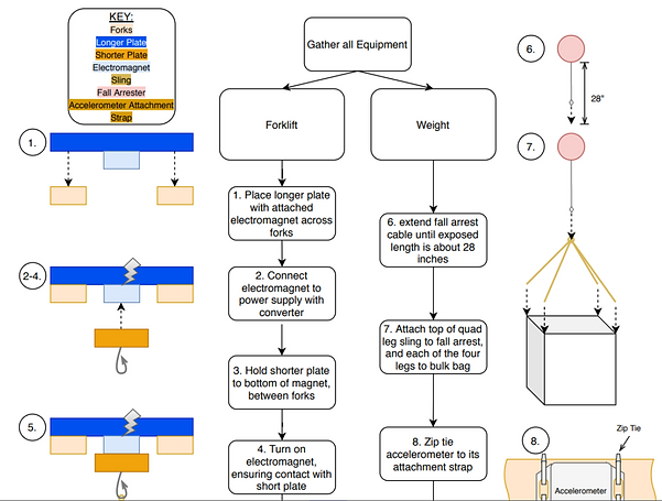
Patient G-Force Test
The purpose of this test was to determine the G-force felt by the patient if the fall arrest safety mechanism was engaged. The test was not completed as a fully loaded assembly was required. A forklift would have been used to lift the bulk bag attached to the extended fall arrest cable, filled, at first, with 3 sandbags (150 lbf.) and then adding more sandbags until 600 lb. was reached. An electromagnet would have been used to allow the forklift to lift the bulk bag and quickly release the bag by cutting the power to the electromagnet.