EML4501 UF MAE Capstone Design - Part 1
University of Florida
January 2020 - April 2020
Executive Summary/
What Was Accomplished
-
Complete design and analysis of a human lift and harness system for the UF Nonlinear Controls and Robotics (NCR) Group, meeting 28 design requirements. The project went through the entire design process, including concept design and down selection, design reviews with engineering faculty, and a final presentation to the customer.
Biggest Takeaways/
Lessons Learned
-
I enjoyed iterating upon the design for the Dynamic Weight Offset mechanism with the engineering faculty in the design reviews; I learned how to prepare for and present engineering analysis for a design review format.
-
During the preliminary design phase, the Covid-19 pandemic began and UF was closed; our team learned to handle communicating, meeting, and using our resources remotely while still achieving the project schedule requirements.
Transferrable
Skills
-
Generating design concepts based on requirements/constraints
-
Determining design features using a quantitative down-selection process
-
Engineering material selection process using Ashby Plots
-
Selecting OTS parts to meet design parameters
-
Generating component and sub-assembly drawings with dimensional tolerances for manufacturing
-
Writing project status reports and technical reports
-
Managing a BOM and manufacturing & assembly costs
-
Creating assembly instructions
Introduction
During the Spring of 2020, I was a part of a 7 member design team focused on delivering a product solution for the UF Nonlinear Controls and Robotics (NCR) Group.
Walking is one of the most fundamental functions of the human condition for a healthy lifestyle. Each year, millions of people suffer from a decreased ability to walk resulting from injury, disease, or other health conditions. Gait training, or physical therapy to assist the patient in their ability to stand and walk, is a popular method to help patients begin to develop or re-gain their independence and confidence in their walking ability following these medical events. If a patient is unable to support some or all their body weight on their legs, a body weight support system (BWS) assists the patient by partially or fully offloading weight to reduce the burden on the patient so they can participate in activities that help coordinate movement of the lower extremities and develop strength and balance in their muscles over time. While many solutions for body weight support systems exist currently on the market, many of the systems are designed for walking, cycling, or treadmill applications and are not capable of suspending the patient at heights suitable for elliptical machine training.
The goal of this EML4501 Capstone Project was to design a human lift and harness system that would interface with an elliptical machine and provide a user-defined partial to full body weight support that automatically adjusts the systems vertical height to accommodate for movement by the patient during the exercise. The NCR group provided a detailed list of 28 requirements and metrics for the design to meet.
Product Overview
The poster below summarizes the product's design and features. View a PDF version here.
During the research and conceptual design phase, the entire team shared equal responsibility in completing deliverables for the project; however, in the preliminary and final design phases, I was primarily responsible for the Dynamic Weight Offset Mechanism.

My Contributions to the Project -
Dynamic Weight Offset Mechanism
Theory of Operation
Once the patient is properly secured onto the elliptical machine and is ready to begin exercising, the Dynamic Weight Offset mode is engaged. The patient’s weight and desired weight offset percentage is entered into the computer system. In this mode the winch is locked; therefore, the cable can no longer retract or advance off the winch. A mechanism within the structure, called the Weight Offset Mechanism, will adjust the tension in the cable to be equal to the desired weight offset. The Weight Offset Mechanism consists of: a ball screw assembly that controls the linear position of a ball screw nut that is mounted to a compression plate, a pulley plate that is coupled to the compression plate by a set of compression springs, a dynamic pulley that is mounted to the pulley plate, and bearings within the plates that allow the plates to slide vertically on a set of rigid rods.
The Weight Offset Mechanism works as follows. First, a sensor reads the current amount of tension in the cable and sends this information to the computer control system. The control system then commands a DC motor to rotate which will advance or retract the ball nut mounted to the compression plate. By adjusting the position of the compression plate, the springs are compressed or decompressed. By taking a force balance of the pulley plate, compression of the springs imposes a spring force against the plate, while the cable imposes a tension force that lifts the pulley plate in the opposite direction; therefore, the force of tension in the cable is equal to the force of the springs, and the spring force is proportional to the spring constant and the amount of spring compression (Hooke’s Law). So, by changing the position of the compression plane, the system is adjusting the amount of tension in the cable. This is done until the sensor reads the desired amount of rope tension.
Once the desired tension is met, the user is given ‘the okay’ to begin the using the elliptical machine. As the patient uses the elliptical, their center of mass will translate vertically, which cause the pulley plate to translate with them and changes the spring length. In order to maintain a constant tension in the cable and therefore a constant unloading force as the patient is moving, a linear position sensor tracks the change in length of the springs and commands the ball screw motor to adjust the position of the compression plate to maintain the desired spring length and cable force. The offset weight support feels continuous to the user despite the vertical motion of their exercise. In short, the offset mechanism converts the desired cable tension control problem into a positional control of the spring element.

Engineering Analysis and Design
In order to size components of the ball screw and motor assembly so that they are fast enough and powerful enough to be able to “keep up” with the speed of the patient, I calculated how fast users on an elliptical move, in particular, how fast their center of mass translates vertically. There is available data for the number of strides per min the average human takes at different levels of intensity when they are running, jogging, or walking. For example, exceptional runners take approximately 180 strides per min, while a brisk walk is generally 100 strides per min. You can relate this fitness intensity to a workout on an elliptical, where one revolution of the machine is two strides. When using an elliptical the user’s center of mass follows a sinusoidal pattern in the vertical plane. Unfortunately, I was not able to find any studies or available data for how much on average that vertical amplitude is, and given the Pandemic at the time I was not able to go out and such collect data for myself, so I estimated this amplitude to be about 2 inches using videos and pixel measurements. The total travel distance per revolution is 8 in/rev --- that is the center of mass goes up 2 inches, down 4 inches, and back up 2 inches. With this information, you can then relate a fitness intensity to a speed of the patient in inches per minute (leaving it in this unit to help us calculate RPM later); however, the required speed of the mechanism is only half of the speed of the user.
The diagram on the right of the slide below quickly explains that working principle. The pulley at the bottom is the one attached to the pulley plate that can translate vertically. Because the length of the rope is to be held constant, only the purple sections of rope can change length. If the length of S1 where to get 4” smaller, the length of S2 would need to get 2” larger, because the setup has two ropes of length S2 in parallel. Even though the mass translates an absolute distance of 4”, the pulley only travels and absolute distance of 2”; therefore, the speed of the mechanism would only need to be half that to keep up with the patient.

Knowing how fast the mechanism will need to operate at to keep up with different fitness intensities, one can calculate the required RPM of the motor that will produce that linear speed that will keep up with the user using equation (1), where the lead is a geometric dimension of the ball screw. An expected range of operating RPM for the motor is produced. Additionally, the motor must provide enough torque in that range of RPM to be able to advance the load, which is the spring force pushing back against the nut. This can be calculated for a range of required torque for different offset loads by equation (2). The selected motor can handle the max condition; however unlikely that is, which would be a 350 lbs. patient requiring 100% of their weight to be offset while also exercising at an exceptional fitness intensity of 1800 RPM; therefore, it can handle all other weight offset loads and speeds.

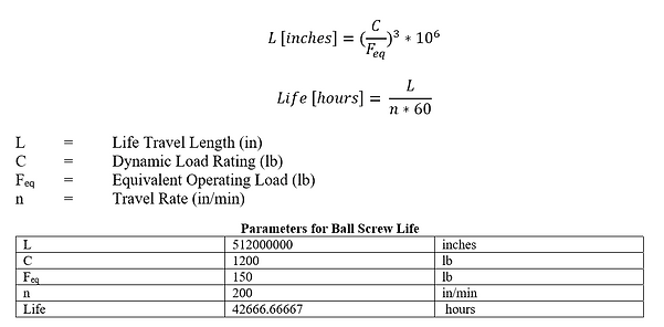
Additional analysis included rating the ball screw and motor components for life, buckling, critical speeds, and other design parameters. The ball nut in tension can handle loads up to the rated capacity of the nut. The selected nut is capable of 9,340 lbf static loading, which has a high factor of safety for the 350 lbf the nut will experience in normal use. Additionally, when the ball nut is loaded in compression, the design must not exceed the recommended maximum compression force, or the screw shaft may buckle. Life of a ball screw assembly is calculated by using the dynamic load rating provided by the vendor. Assumptions were made about the equivalent operating load and travel rate, as those variables are not constant for this application, so the average value was chosen. Converting the life into years, the ball screw motor is rated for approximately 40 years of use if used for 3 hours/day.


The ball screw assembly must also be evaluated for critical speed calculations. There is a rotational limit for the ball screw, which is related to the natural frequency of the screw shaft. If exceeded, the shaft will have excessive vibration and harmonics in the screw can result in fracture failure of the assembly. The max operating motor RPM is 1800 RPM; therefore, the FOS is 2.68.
Additionally, exceeding the critical nut speed can permanently damage the ball recirculation components. A DN value of less than 3000 is considered standard, per the vendor. Given the nominal diameter is 0.5 and the max RPM is 1800, the DN of 900 results in a FOS of 3.33.

Additional analysis included strength analysis of the Cable and Pulley system. Wire rope is the preferred mechanical lifting device for this application, as its structure provides high strength and flexibility. A coating should be applied to the wire rope to prevent any abrasive injury should the rope contact the patient or therapists during the physical therapy session. Nylon is hard material coating that has a good impact, abrasion, and fatigue resistance. The coating be clear in order to be able to inspect the wire ripe for fraying and indications at a periodic frequency.
The minimum breaking strength of wire rope is the minimum amount of weight that can be applied to the wire rope that would result in failure. It is recommended to stay below a working load limit (WLL), or the maximum load that can be applied without risking tensile or material failure, which is determined by selecting a factor of safety that is unique to individual applications. For standard hoisting a factor of safety of 5 is used, and for applications that are of danger to human life, factors of safety of up to 8 or 9 in other industries.
The selected wire rope is: 7x19 Commercial Aircraft Cable Flexible Preformed Galvanized Zinc Coated Carbon Steel, Clear Nylon Coating; Wire Diameter 5/32, Nylon Diameter 7/32. Minimum Break Strength 2,800 lbs. This wire rope maintains a factor of safety of 8 given the maximum patient load of 350 lbs.
To prevent early fatigue of wire ropes, it is important to use sheaves/pulleys of adequate size. A recommended minimum tread diameter is provided by the manufacturer to select an adequate pulley size so that the wire rope meets the performance specifications. The selected wire rope diameter is 5/32, so the desirable minimum tread diameter for the pulley is 3-3/4” and the critical minimum tread diameter is 2-7/8” for 7x19 wire rope type. The selected pulley is: 5” OD Pulley for Wire Rope w/ Bearing, 4-3/8” Pulley Diameter, Shaft Diameter 3/4”, for 1/4” Wire Rope Diameter; Load Capacity 1,400 lbs. The pulley diameter is greater than the minimum desirable tread diameter stated previously.

A final analysis determined the required features for the springs. Consider a free body diagram of the pulley plate as the patient’s center of gravity is at the lowest point during their exercise. In this condition, the pulley plate will move in the positive y-direction. Taking the sum of the forces in the y-direction:


Where FT is the force of tension in the cable, which assumes that the rotational inertia and friction of the pulleys are negligible. Fs is the spring force that acts on the plate when the spring is compressed. Given that the force of friction (Ff) in the plate sliding along the rigid rods is reduced significantly by the linear bearings, and that the inertia of the plate is minimal since patients undergoing gait therapy are generally slow moving, it can be assumed that these values are relatively small compared with that of the tension of the cable and can be negated from the analysis. The weight of the aluminum plates are 3lb, which is minimal but not necessarily negligible; however, the weight of the plate is constant and can and programmed into the control system of the motor to compensate for this additional weight. Thus, the cable force can be approximated using Hooke’s Law as:

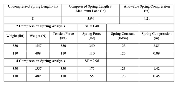
In conclusion, to maintain a constant tension in the cable (and therefore a constant offset weight support), a constant spring force must be applied to the pulley plate as it moves. To maintain a constant spring force, a constant spring length must be maintained. In order to be able to support the maximum allowable patient, the selected set of compression springs must allow for 100% dynamic weight offset of a 350 lbs patient. Using parameters such as uncompressed spring length, the maximum compression spring length, and the spring constant provided by the manufacturer McMaster-Carr, calculations can be performed to determine the allowable spring compression, the required spring compression to offset 350lbs, and the safety factor of the spring set. The analysis is performed for a set of 2 compression springs as well as a set of 4 compression springs to test different configurations of the design. For a set of 4 compression springs, the required spring force is reduced by half. Additionally, the required spring compression for the minimum 110 lbs. patient, or average weight of a 5th percentile female over the age of 20, is also determined to help visualize the minimum expected spring compressions. The following variables and equations are set up in a spreadsheet in order to test many spring options and optimize each of these parameters. The selected spring is a pair of two Spring-Tempered Steel Compression Springs 8" Long, 2.438" OD, 1.814" ID. The results of the analysis for this spring are presented below. The variable and equations are as follows:


Assembly BOM
Conclusion
I am very grateful to have worked with a hardworking and talented team, as well as to have support from the UF engineering faculty during the design process. View part two of the project, the manufacturing and testing phase, here.
